Friday, March 26, 2010

Monitoring Virtual Routers

Use the show virtual-router and show aaa domain-map commands to display virtual router and user-domain-to-virtual-router mapping information. Use the show ip forwarding table command to display information about memory usage by virtual routers.

show aaa domain-map

  • Use to display the mapping between user domains and virtual routers.
  • The following keywords have significance when used as user domains:
  • none—All client requests with no user domain name are associated with the virtual router mapped to the none entry
  • default—All client requests with a domain present that has no map are associated with the virtual router mapped to the default entry
  • Example
  • host1#show aaa domain-map
    Domain: boston; virtual-router: default

    Tunnel Tunnel Tunnel Tunnel Tunnel  Tunnel   Tunnel  Tunnel
     Tag    Peer  Source  Type  Medium Password   Id    Hostname
    ------ ------ ------ ------ ------ --------  ------ --------
    31       l2tp   ipv4        

             Tunnel
    Tunnel   Server     Tunnel
     Tag      Name    Preference
    ------   ------   ----------
    31          2000

show configuration virtual-router

  • Use to display configuration information for the virtual routers configured on your router.
  • You can create a configuration script from the output by saving it as a file with the .scr extension.
  • You can exclude information about a particular type of interface.
  • You can use the output filtering feature of the show command to include or exclude lines of output based on a text string you specify. See Chapter 2, Command-Line Interface, for details.
  • Example
  • host1#show configuration virtual-router default
    virtual-router default
    ip domain-lookup
    ip name-server 10.2.0.3
    ip domain-name "junipercom.com"
    !
    host f 10.10.0.129 ftp anonymous null
    interface null 0
    !
    interface fastEthernet 0/0
     ip address 192.168.1.155 255.255.255.0
    !
    ip route 0.0.0.0 0.0.0.0 192.168.1.1
    no ip multicast-routing
    !
    mpls rsvp profile default
    mpls ldp profile default
     cr-ldp
    !
    rtr 1
     type echo protocol ipIcmpEcho 10.5.0.200 source fastEthernet0/0
     frequency 1
     samples-of-history-kept 5
     timeout 10000
    !

show ip forwarding-table slot

  • Use to display the memory used by each VR configured on a line module and free memory available on the line module.
  • Field descriptions
  • Free Memory—Amount of memory free on the line module, in kilobytes
  • Virtual Router—Name of the virtual routers configured on the line module
  • Memory (KB)—Amount of memory consumed by the VR, in kilobytes
  • Load Errors—Counts errors made while loading the routing table on the line module
  • Status—Indicates whether the routing table for the VR is valid
  • Example
  • host1#show ip forwarding-table slot 9
    Free Memory = 14,328KB
      Virtual Router      Memory       Load Errors     Status
                          (KB)
    ----------------     ---------    -------------    --------
       vr1                 4128              0          Valid
       vr2                 3136              0          Valid
       vr3                 2256              0          Valid
       vr4                 1512              0          Valid
     default               1024              0          Valid
    -----------------------------------------------------------

show virtual-router

  • Use to display the virtual routers and VRFs configured on your router.
  • Use the summary keyword to display only the total number of virtual routers and the total number of VRF instances.
  • Use the detail keyword to display the status of the routing protocols configured for each virtual router.
  • Use the summary keyword with the detail keyword to display the number of VRF instances for each virtual router.
  • You can use the output filtering feature of the show command to include or exclude lines of output based on a text string you specify. See Chapter 2, Command-Line Interface, for details.
  • Example 1
  • host1#show virtual-router
    Virtual Router : default
    Virtual Router : vr1
                     VRF : eastern
                     VRF : western
                     VRF : northern
                     VRF : southern
    Virtual Router : vr2
                     VRF : eastern
                     VRF : western
                     VRF : northern
                     VRF : southern
    Virtual Router : vr3
                     VRF : eastern
                     VRF : western
                     VRF : northern
                     VRF : southern

  • Example 2
  • host1#show virtual-router detail
    Virtual Router : default
                            Ip:     Present
                            Ipv6:   Not Present
                            Mgtm:   Not Present
                            Mgtmv6: Not Present
                            Bgp:    Not Present
                            Isis:   Present
                            Ospf:   Not Present
                            Pim:    Not Present
                            Rip:    Not Present
                            Igmp:   Not Present
                            Mld:    Not Present
                            Dvmrp:  Not Present
    Virtual Router : vr1
                            Ip:     Present
                            Ipv6:   Not Present
                            Mgtm:   Present
                            Mgtmv6: Not Present
                            Bgp:    Not Present
                            Isis:   Present
                            Ospf:   Present
                            Pim:    Present
                            Rip:    Not Present
                            Igmp:   Not Present
                            Mld:    Not Present
                            Dvmrp:  Not Present

  • Example 3
  • host1#show virual-router summary detail
    Virtual Router default                          VRF Count: 0
    Virtual Router vr1                              VRF Count: 4
    Virtual Router vr2                              VRF Count: 4
    Virtual Router vr3                              VRF Count: 4

    Total VR Count: 4
            VRs with    VRFs Count: 3
            VRs without VRFs Count: 1
    Total VRF Count: 12
    Total Count    : 16

Configuring Virtual Routers

There are different uses of the virtual-router command. You can create or access VRs and VRFs in Global Configuration mode or map a VR to a domain map in Domain Map Configuration mode. Once you create a VR, you can continue to work in different command modes and configure the same user interface parameters as before the virtual router was created.


Create and name a VR in Configuration mode.
host1(config)#virtual-router western
  • reate a VRF to provide forwarding information to your router. In this example, the VRF created is in context with the VR created above.
  • host1:western(config)#ip vrf eastern
    Proceed with new VRF creation? [confirm]
    host1:western(config-vrf)#virtual-router:eastern
    host1:western:eastern(config)#

  • Access a VRF from th


    e context of a different VR.
  • host1(config)#virtual-router western:eastern
ew your configuration choices from a VR or VRF context.

host1:western:eastern(config)#?
  aaa                      Configure authentication, authorization,
                           and accounting characteristics
  access-list              Configure an access list entry
  arp                      Configure a static ARP entry
  bandwidth                Configure slot-group bandwidth control
  banner                   Define a banner line
  baseline                 Configure baseline operations
  boot                     Configure boot time behavior
  bulkstats                Configure bulkstats parameters
  cbf                      Configure connection-based forwarding
  classifier-list          Configure a classifier list entry
  clns                     Configure CLNS characteristics
  clock                    Set the system's clock
  controller               Configure controller parameters
  crypto                   Configure cryptographic parameters
  disable-autosync         Disable automatic synchronization of
                           redundant system controller file system
  disable-switch-on-error  Disable automatic switch to redundant system
                           controller upon software/hardware error
  enable                   Configure security related options
  end                      Exit Global Configuration mode
  exception                Configure core dump
  exclude-subsystem        Exclude copying a subsystem from the release
  exit                     Exit from the current command mode
  ftp-server               Configure FTP Server characteristics
  help                     Describe the interactive help system
  host                     Add/modify an entry to the host table
  hostname                 Set the host (system) name
  interface                Enter Interface Configuration mode
  ip                       Configure IP characteristics
  l2tp                     Configure L2TP parameters
  license                  Configure licenses
  line                     Enter Line Configuration mode
  log                      Configure logging settings
  macro                    Run a CLI macro
  map-list                 Create an NBMA static map
  memory                   Configure and administer memory operations
  mpls                     Configure MPLS global parameters
  no                       Negate a command or set its default(s)
  ntp                      Configure the Network Time Protocol
  policy-list              Enter Policy Configuration mode
  pppoe                    Configure PPPoE
  profile                  Specify a profile
  radius                   Configure RADIUS server
  rate-limit-profile       Enter rate limit profile configuration mode
  redundancy               Perform a redundancy configuration
  route-map                Configure a route map
  router                   Configure a routing protocol
  rtr                      Configure rtr parameters
  service                  Configure system-level services
  set                      Configure
  sleep                    Make the Command Interface pause for a
                           specified duration
  slot                     Configure and administer slot operation
  snmp-server              Configure SNMP parameters
  sscc                     The SSC Client
  telnet                   telnet daemon configuration
  timing                   Configure network timing
  traffic-shape-profile    Enter traffic shape profile configuration mode
  virtual-router           Specify a virtual router
host1:western:eastern(config)#

  • View the VRF configuration choices from VRF Configuration mode.
  • host1:western(config-vrf)#?
      exit          Exit from the current command mode
      export        Specify VRF export characteristics
      help          Describe the interactive help system
      import        Specify VRF import characteristics
      log           Configure logging settings
      macro         Run a CLI macro
      no            Negate a command or set its default(s)
      rd            Specify route distinguisher
      route-target  Specify VPN extended community Target
      sleep         Make the Command Interface pause for a
                     specified duration
    host1:western(config-vrf)#

  • Access a VR to configure it with an interior gateway protocol (IGP) or exterior gateway protocol (EGP) to learn routes from a customer edge device (CE). See the related routing protocol chapters for detailed information.

Example 1
VR with an IGP

host1(config)#virtual-router miami
host1:miami(config)#router ospf 5
host1:miami(config-router)#

Example 2
VR with an EGP

host1(config)#virtual-router western
host1:western(config)#router bgp 359
host1:western(config-router)#

  • Configure a Telnet daemon to listen in VRs other than the default VR.
  • host1(config)#virtual-router boston
    host1:boston(config)#telnet listen port 23

  • List all VRs and VRFs on the router.
  • host1#show virtual-router
    Virtual Router : default
    Virtual Router : thursday
    Virtual Router : western
                     VRF : eastern
    Virtual Router : boston
    Virtual Router : miami
    Virtual Router : northern
                     VRF : southern
    host1#

  • Map a VR to a user domain name in Domain Map Configuration mode. The VR must already exist.
  • host1(config)#aaa domain-map jacksonville
    host1(config-domain-map)#virtual-router western
    host1(config-domain-map)#

aaa domain-map

  • Use to map a user domain name to a virtual router.
  • Examples
  • host1-0-1-90(config)#aaa domain-map juniper.net vrouter_1
    host1-0-1-90(config)#aaa domain-map none vrouter__all_purpose
    host1-0-1-90(config)#aaa domain-map DEFAULT vrouter_all_purpose

  • Use the no version of the command to delete the domain map.

ip vrf

  • Use to create a VRF or access VRF Configuration mode to configure a VRF.
  • You must specify a route distinguisher after you create a VRF. Otherwise, the VRF will not operate.
  • Example
  • host1-00-02-80:boston(config)#ip vrf vpn-A

  • Use the no version to remove a VRF.

telnet listen

  • Use to create a Telnet daemon to listen in a virtual router.
  • Example
  • host1(config)#virtual-router 3
    host1:3(config)#telnet listen port 3223

  • Use the no version of the command to delete the daemon.

virtual-router

  • From Global Configuration mode, use this command to create a virtual router or access the context of a previously created virtual router or a VRF.
  • From Domain Map Configuration mode, use this command to map the VR to a user domain name. Use the no version in this mode to delete the VR parameter and assign the default VR.
  • A VR name consists of 1-32 alphanumeric characters.
  • Once you are in the context of a particular VR or VRF (indicated by the change in the prompt), all subsequent commands you enter apply to that context until you exit the context.
  • Use the no version of the command only to delete the VR and return the router to the default VR. Issuing the command no virtual-router vrName.vrfName has no effect.
  • Issuing a no version of this command (no virtual-router :vrfName or no virtual-router vrName:vrfName) that specifies an existing VRF only displays the error message: "Cannot delete a VRF with this command." You must use the no ip vrf command to remove a VRF.

    NOTE: See JUNOSe Command Reference Guide for additional information.


  • Use the wait-for-completion keyword with the no version if you require a synchronous, deterministic deletion of a VR, such as when executing Telnet or console commands through an external script. Alternatively, you might want to use this keyword if the VR being deleted has many configured VRFs and someone might attempt to recreate the VR before all the VRFs have been deleted. If you do not issue the wait-for-completion keyword in those circumstances, a virtual-router command issued as soon as the prompt appears could fail because the router is still deleting VRFs. You can specify a period during which the CLI waits before it returns a prompt. If you do not specify a wait time, then the CLI does not return a prompt until the operation completes. You can press Ctrl+c to break out of the wait period early.

Show vrf command

show ip vrf [options] [vrf_name]

Common options include;

  • brief - display brief VRF information (name, RD and interfaces) - this is the default output if no options are used
  • detail - display detailed VRF information
  • id - display VPN routing/forwarding VPN-ID information
  • interfaces - display information on VRF enabled interfaces

Image:Vm-power-on-medium.png Usage Examples

show ip vrf - display brief VRF information

show ip vrf detail vrftest - display detailed VRF information for the VRF named testvrf only

Image:utilities-terminal-medium.png Typical Output

show ip vrf;

Name                             Default RD          Interfaces
vrftest Gi0/5
Gi0/6

show ip vrf detail vrftest;

VRF vrftest; default RD ; default VPNID 
Description: Test VRF
Interfaces:
Gi0/5 Gi0/6
Connected addresses are not in global routing table
No Export VPN route-target communities
No Import VPN route-target communities
No import route-map
No export route-map
VRF label distribution protocol: not configured
VRF label allocation mode: per-prefix

show ip vrf interfaces;

Interface              IP-Address      VRF                              Protocol
Gi0/5 1.6.2.2 vrftest up
Gi0/6 1.6.2.139 vrftest up

Monday, March 22, 2010

valn routing

PowerConnect Application Note #38 February 2004
www.dell.com/networking 1
What is VLAN Routing?
This Application Notes relates to the following Dell PowerConnect™ product(s):
• PowerConnect 6024 and 6024F
• PowerConnect 33xx
Abstract
Virtual LANs (VLANs) offer a method of dividing one physical network into multiple broadcast domains.
However, VLAN-enabled switches cannot, by themselves, forward traffic across VLAN boundaries. For
inter-VLAN communication, a Layer 3 router is required. This document discusses the VLAN protocol and
provides step-by-step instructions for configuring VLAN routing using the Dell PowerConnect 6024 and
PowerConnect 33xx switches.
Applicable Network Scenarios
As shown in the figure below, the addition of a router makes it possible to send traffic between VLANs
while still containing broadcast traffic within VLAN boundaries.
The router uses IP subnets to move traffic between VLANs. Each VLAN has a different IP subnet, and
there is a one-to-one correspondence of VLAN and IP subnet boundaries. If a host is in a given IP subnet,
it is also in a given VLAN, and vice-versa.
A
C
B
D
Layer 2 Switch Layer 2 Switch
VLAN Trunks
VLANs 10 & 20
Layer 3 Router
VLAN 10
VLAN 20
If host A needs to communicate with host D, it first sends an address resolution protocol (ARP) frame with
host D’s destination IP address and a broadcast MAC address. The switch forwards this broadcast to all
other ports in VLAN 10, including the one attached to the router. The router, recognizing that it can reach
host D’s network, will send an ARP response frame with its own MAC address as the destination MAC
address host A should use.
PowerConnect Application Note #38: VLAN Routing
www.dell.com/networking 2
For all subsequent traffic, host A will send frames with host D’s IP address but the router’s MAC address.
The router, knowing that the destination network is on VLAN 20, will route the frame to the switch with a
VLAN ID of 20. The switch, in turn, will deliver the frame to host D.
The true benefits of VLANs are now realized: Bandwidth consumption is kept to a minimum by preventing
cross-VLAN broadcast traffic, but hosts in different VLANs are still able to communicate through the use
of a router.
In networks with a central server running Dynamic Host Configuration Protocol (DHCP), the router can be
configured to relay DHCP requests from each subnet. The DHCP server would be configured to assign IP
addresses based on the origin IP subnet.
Technology Background
As defined in IEEE standard 802.1Q, virtual LANs offer a method of dividing one physical network into
multiple broadcast domains. In enterprise networks, these broadcast domains usually match with IP
subnet boundaries, so that each subnet has its own VLAN.
To identify traffic belonging to different VLANs, the 802.1Q standard defines a method called VLAN
tagging. With tagging, switches insert a 4-byte VLAN tag into the header of each frame. The tag contains
a 12-bit “VLAN ID” that identifies the frame’s VLAN membership.
Dell PowerConnect 33xx switches offer three main modes for handling VLAN traffic on a given interface.
Access mode specifies a single, untagged VLAN to which the interface belongs; this is useful when the
attached host is a PC or server.
General mode allows the administrator to configure multiple VLANs that can be tagged or untagged; this
is useful for nodes that must communicate on more than one VLAN.
Trunk mode inserts a VLAN tag into all frames; this is useful for inter-switch trunk links that carry traffic
between multiple VLANs over a single link.
Since switches only forward broadcast traffic within VLAN boundaries, we can see that VLANs help
reduce the amount of extraneous network traffic and free up processing resources on attached hosts.
However, when traffic needs to cross a VLAN boundary, a router is required.
When a switch receives a frame from one VLAN destined for another VLAN, the switch forwards the
frame to a router. The router, if properly configured, will then route the frame between subnets, and
forward the frame to the interface associated with the destination VLAN.
As noted, inter-VLAN routing allows hosts in all VLANs to obtain addresses using DHCP. The Internet
Engineering Task Force described DHCP for IP version 4 in Request for Comments 2131 (RFC 2131).
The router must be configured to relay requests to the DHCP server in cases where the DHCP server is
not on a directly attached subnet.
Proposed Solution
Overview
In the following example, we will configure a Dell PowerConnect 6024 to route traffic between VLANs 10
and 20, with hosts in each VLAN attached to a Dell PowerConnect 3348. The network topology is
identical to that given previously in the Applicable Network Scenarios section of this document with one
addition: Hosts in VLANs 10 and 20 get their IP addresses from a central DHCP server.
PowerConnect Application Note #38: VLAN Routing
www.dell.com/networking 3
The steps we use are:
1. Create VLANs on the router
2. Assign IP addresses to the each VLAN on the router.
3. Configure the router port connected to the switch as a VLAN trunk port.
4. Define routes to each network.
5. Configure the router to relay DHCP requests.
6. Create the VLANs on the switch.
7. Configure the switch port connected to the router as a VLAN trunk.
8. Add switch access ports to the appropriate VLANs.
The following example uses three IP subnets. The router associates VLANs 10 and 20 with 10.10.0.0/24
and 10.20.0.0/24, respectively. The DHCP server is on 10.100.0.0/24, a subnet which is not directly
attached to the router. In this example, we assume the router can reach the 10.100.0.0 subnet via static
or dynamically learned routing information.
The DHCP server must be configured to respond to DHCP requests on the appropriate subnet. For
example, if the DHCP server receives a request forwarded from the router’s 10.10.0.0/24 subnet, it must
respond with an address on that subnet. DHCP server configuration is beyond the scope of this
Application Note.
A
C
B
D
PowerConnect
3348
PowerConnect
3348
VLAN Trunks
VLANs 10 & 20
PowerConnect
6024
g23 g24
1/e10
1/e1
1/e2
1/e10
1/e1
1/e2
VLAN 20 / 10.20.0.0/24
VLAN 10 / 10.10.0.0/24
DHCP Server
10.100.0.100/24
Step-By-Step Instructions
1. Create VLANs on the router.
Dell-6024> enable
Dell-6024# configure
Dell-6024(config)# vlan database
Dell-6024(config-vlan)# vlan 10
Dell-6024(config-vlan)# vlan 20
Dell-6024(config-vlan)# exit
2. Assign IP addresses to the each VLAN on the router.
Dell-6024(config)# interface vlan 10
Dell-6024(config-if)# ip address 10.10.0.1 /24
Dell-6024(config-if)# exit
PowerConnect Application Note #38: VLAN Routing
www.dell.com/networking 4
Dell-6024(config)# interface vlan 20
Dell-6024(config-if)# ip address 10.20.0.1 /24
Dell-6024(config-if)# exit
3. Configure the router port connected to the switch as a VLAN trunk port. We use interface g24.
Dell-6024(config)# interface ethernet g(23-24)
Dell-6024(config-if)# switchport mode trunk
Dell-6024(config-if)# switchport trunk allowed vlan add 10,20
Dell-6024(config-if)# exit
4. Define routes to each network.
Dell-6024(config)# ip route 10.10.0.0 255.255.255.0 10.10.0.2
Dell-6024(config)# ip route 10.20.0.0 255.255.255.0 10.20.0.2
As noted, we assume the router has previously been configured to reach the DHCP server on the
10.100.0.0/24 subnet.
5. Configure the router to relay DHCP requests.
Dell-6024(config)# ip dhcp relay enable
Dell-6024(config)# ip dhcp relay address 10.100.0.100
Dell-6024(config)# exit
Dell-6024# copy running-config startup-config
This concludes the configuration of the router. Now we will configure the PowerConnect 3348 switches.
6. Create the VLANs on the switches. On the first (left) switch in the figure:
Dell-3348-1> enable
Dell-3348-1# configure
Dell-3348-1(config)# vlan database
Dell-3348-1(config-vlan)# vlan 10
Dell-3348-1(config-vlan)# vlan 20
Dell-3348-1(config-vlan)# exit
On the second (right) switch in the figure:
Dell-3348-2> enable
Dell-3348-2# configure
Dell-3348-2(config)# vlan database
Dell-3348-2(config-vlan)# vlan 10
Dell-3348-2(config-vlan)# vlan 20
Dell-3348-2(config-vlan)# exit
7. Configure the switches port connected to the router as a VLAN trunk. We use interface 1/e10. On the
first (left) switch in the figure:
Dell-3348-1(config)# interface ethernet 1/e10
Dell-3348-1(config-if)# switchport mode trunk
Dell-3348-1(config-if)# switchport trunk allowed vlan add 10,20
Dell-3348-1(config-if)# exit
On the second (right) switch in the figure:
Dell-3348-2(config)# interface ethernet 1/e10
Dell-3348-2(config-if)# switchport mode trunk
PowerConnect Application Note #38: VLAN Routing
www.dell.com/networking 5
Dell-3348-2(config-if)# switchport trunk allowed vlan add 10,20
Dell-3348-2(config-if)# exit
8. Configure access ports in the appropriate VLANs. We attach host A to interface 1/e1 and host C to
interface 1/e2 on switch 1. We attach host B to interface 1/e1 and host D to interface 1/e2 on switch 2.
On the first (left) switch in the figure:
Dell-3348-1(config)# interface ethernet 1/e1
Dell-3348-1(config-if)# switchport mode access
Dell-3348-1(config-if)# switchport access vlan 10
Dell-3348-1(config-if)# exit
Dell-3348-1(config)# interface ethernet 1/e2
Dell-3348-1(config-if)# switchport mode access
Dell-3348-1(config-if)# switchport access vlan 20
Dell-3348-1(config-if)# end
Dell-3348-1# copy running-config startup-config
On the second (right) switch in the figure:
Dell-3348-2(config)# interface ethernet 1/e1
Dell-3348-2(config-if)# switchport mode access
Dell-3348-2(config-if)# switchport access vlan 10
Dell-3348-2(config-if)# exit
Dell-3348-2(config)# interface ethernet 1/e2
Dell-3348-2(config-if)# switchport mode access
Dell-3348-2(config-if)# switchport access vlan 20
Dell-3348-2(config-if)# end
Dell-3348# copy running-config startup-config
Conclusion
The network can now route traffic between VLANs. This is a scalable solution: As new VLANs are added,
network managers can simply define additional routes on the PowerConnect 6024.
Information in this document is subject to change without notice.
© 2004 Dell Inc. All rights reserved.
This Application Note is for informational purposes only, and may contain typographical errors and technical inaccuracies. The
content is provided as is, without express or implied warranties of any kind.
Trademarks used in this text: Dell, the DELL logo, and PowerConnect are trademarks of Dell Inc. Other trademarks and trade
names may be used in this document to refer to either the entities claiming the marks and names or their products. Dell Inc.

Why use loopback

The Loopback interface can be used when you need an "always up" interface as the end-point for a tunnel or IBGP session. When a physical interface goes down, it causes the tunnel or BGP session to terminate. Using a Loopback interface moves the connection to an interface which never stops working. Another benefit is that any alternate routes to the Loopback interface will allow the tunnel or BGP session to continue to operate even when an interface dies.

The Loopback interface can also be used with OSPF to select a router ID that is not tied to a physical interface or to force a different router ID. The Loopback interface address is always selected as the router ID for OSPF, even if other interfaces have a higher IP address. If multiple Loopback interfaces exist, the first Loopback interface is used.

To configure a Loopback interface, use the following configuration:

interface loopback 0
ip address 1.2.3.4 255.0.0.0

Search for "loopback interface" in UniverCD for details and other configuration options.


cable category

Category 1—Used for telephone communications. Not suitable for transmitting data.

Category 2—Capable of transmitting data at speeds up to 4 megabits per second (Mbps).

Category 3—Used in 10BASE-T networks. Can transmit data at speeds up to 10 Mbps.

Category 4—Used in Token Ring networks. Can transmit data at speeds up to 16 Mbps.

Category 5—Can transmit data at speeds up to 100 Mbps.

Category 5e —Used in networks running at speeds up to 1000 Mbps (1 gigabit per second [Gbps]).

Category 6—Typically, Category 6 cable consists of four pairs of 24 American Wire Gauge (AWG) copper wires. Category 6 cable is currently the fastest standard for UTP


Saturday, March 20, 2010

vrf manual

Manual:Virtual Routing and Forwarding

From MikroTik Wiki

Jump to: navigation, search

Applies to RouterOS: 3, v4

Packages required: routing-test, mpls-test for RouterOS v3; routing, mpls for RouterOS v4+

Contents

[hide]

Description

RouterOS 3.x allows to create multiple Virtual Routing and Forwarding instances on a single router. This is useful for BGP based MPLS VPNs. Unlike BGP VPLS, which is OSI Layer 2 technology, BGP VRF VPNs work in Layer 3 and as such exchange IP prefixes between routers. VRFs solve the problem of overlapping IP prefixes, and provide the required privacy (via separated routing for different VPNs).

To create a VRF, configure it under /ip route vrf. You can now add routes to that VRF - simply specify routing-mark attribute. Connected routes from interfaces belonging to a VRF will be installed in the right routing table automatically.

Technically VRFs are based on policy routing. There is exactly one policy route table for each active VRF. The existing policy routing support in MT RouterOS is not changed; but on the other hand, it is not possible to have policy routing within a VRF. The main differences between VRF tables and simple policy routing are:

  • Routes in VRF tables resolve next-hops in their own route table by default, while policy routes always use the main route table. Read-only route attribute gateway-table displays information about which table is used for a particular route (default is main).
  • Route lookup is different. For policy routing: after route lookup has been done in policy-route table, and no route was found, route lookup proceeds to the main route table. For VRFs: if lookup is done, and no route is found in VRF route table, the lookup fails with "network unreachable" error. (You can still override this behavior with custom route lookup rules, as they have precedence.)

You can use multi-protocol BGP with VPNv4 address family to distribute routes from VRF route tables - not only to other routers, but also to different routing tables in the router itself. First configure the route distinguisher for a VRF. It can be done under /ip route vrf. Usually there will be one-to-one correspondence between route distinguishers and VRFs, but that's not a mandatory requirement. Route installation in VRF tables is controlled by BGP extended communities attribute. Configure import and export lists under /ip route vrf, import-route-targets and export-route-targets. Export route target list for a VRF should contained at least the route distinguisher for that VRF. Then configure a list of VRFs for each BGP instance that will participate in VRF routing.

Once list of VRFs for BGP instance, route distinguisher and export route targets has been configured, some active VPNv4 address family routes may be created, depending on BGP redistribution settings. They are installed in a separate route table and, if present, visible under /routing bgp vpnv4-route. These so called VPNv4 routes have prefix that consists of a route distinguisher and an IPv4 network prefix. This way you can have overlapping IPv4 prefixes distributed in BGP.

Please note that a VPNv4 route will be distributed only if it has a valid MPLS label. You need to install mpls-test package and configure valid label range for this to work. (Default configuration has valid label range.)

Examples

The simplest MPLS VPN setup

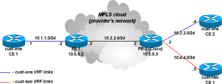
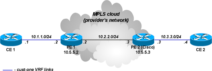
In this example rudimentary MPLS backbone (consisting of two Provider Edge (PE) routers PE1 and PE2) is created and configured to forward traffic between Customer Edge (CE) routers CE1 and CE2 routers that belong to cust-one VPN.

CE1 Router

/ip address add address=10.1.1.1/24 interface=ether1
# use static routing
/ip route add dst-address=10.3.3.0/24 gateway=10.1.1.2

CE2 Router

/ip address add address=10.3.3.4/24 interface=ether1
/ip route add dst-address=10.1.1.0/24 gateway=10.3.3.3

PE1 Router

/interface bridge add name=lobridge
/ip address add address=10.1.1.2/24 interface=ether1
/ip address add address=10.2.2.2/24 interface=ether2
/ip address add address=10.5.5.2/32 interface=lobridge
/ip route vrf add disabled=no routing-mark=cust-one route-distinguisher=1.1.1.1:111 \
export-route-targets=1.1.1.1:111 import-route-targets=1.1.1.1:111 interfaces=ether1
/mpls ldp set enabled=yes transport-address=10.5.5.2
/mpls ldp interface add interface=ether2
/routing bgp instance set default as=65000
/routing bgp instance vrf add instance=default routing-mark=cust-one redistribute-connected=yes
/routing bgp peer add remote-address=10.5.5.3 remote-as=65000 address-families=vpnv4 \
update-source=lobridge
# add route to the remote BGP peer's loopback address
/ip route add dst-address=10.5.5.3/32 gateway=10.2.2.3

PE2 Router (Cisco)

ip vrf cust-one
rd 1.1.1.1:111
route-target export 1.1.1.1:111
route-target import 1.1.1.1:111
exit

interface Loopback0
ip address 10.5.5.3 255.255.255.255

mpls ldp router-id Loopback0 force
mpls label protocol ldp

interface FastEthernet0/0
ip address 10.2.2.3 255.255.255.0
mpls ip

interface FastEthernet1/0
ip vrf forwarding cust-one
ip address 10.3.3.3 255.255.255.0

router bgp 65000
neighbor 10.5.5.2 remote-as 65000
neighbor 10.5.5.2 update-source Loopback0
address-family vpnv4
neighbor 10.5.5.2 activate
neighbor 10.5.5.2 send-community both
exit-address-family
address-family ipv4 vrf cust-one
redistribute connected
exit-address-family

ip route 10.5.5.2 255.255.255.255 10.2.2.2

Results

Check that VPNv4 route redistribution is working:

[admin@PE1] > /routing bgp vpnv4-route print detail
Flags: L - label present
0 L route-distinguisher=1.1.1.1:111 dst-address=10.3.3.0/24 gateway=10.5.5.3
interface=ether2 in-label=17 out-label=17 bgp-local-pref=100 bgp-med=0
bgp-origin=incomplete bgp-ext-communities="RT:1.1.1.1:111"

1 L route-distinguisher=1.1.1.1:111 dst-address=10.1.1.0/24 interface=ether1
in-label=16 bgp-ext-communities="RT:1.1.1.1:111"

Check that the 10.3.3.0 is installed in IP routes, in cust-one route table:

[admin@PE1] > /ip route print
Flags: X - disabled, A - active, D - dynamic,
C - connect, S - static, r - rip, b - bgp, o - ospf, m - mme,
B - blackhole, U - unreachable, P - prohibit
# DST-ADDRESS PREF-SRC GATEWAY DISTANCE
0 ADC 10.1.1.0/24 10.1.1.2 ether1 0
1 ADb 10.3.3.0/24 10.5.5.3 recursi... 20
2 ADC 10.2.2.0/24 10.2.2.2 ether2 0
3 ADC 10.5.5.2/32 10.5.5.2 lobridge 0
4 A S 10.5.5.3/32 10.2.2.3 reachab... 1

Let's take closer look at IP routes in cust-one VRF. The 10.1.1.0/24 IP prefix is a connected route that belongs to an interface that was configured to belong to cust-one VRF. The 10.3.3.0/24 IP prefix was advertised via BGP as VPNv4 route from PE2 and is imported in this VRF routing table, because our configured import-route-targets matched the BGP extended communities attribute it was advertised with.

[admin@PE1] /ip route> print detail where routing-mark=cust-one
Flags: X - disabled, A - active, D - dynamic,
C - connect, S - static, r - rip, b - bgp, o - ospf, m - mme,
B - blackhole, U - unreachable, P - prohibit
0 ADC dst-address=10.1.1.0/24 pref-src=10.1.1.2 gateway=ether1 distance=0 scope=10
routing-mark=cust-one

1 ADb dst-address=10.3.3.0/24 gateway=10.5.5.3 recursive via 10.2.2.3 ether2
distance=20 scope=40 target-scope=30 routing-mark=cust-one
bgp-local-pref=100 bgp-origin=incomplete
bgp-ext-communities="RT:1.1.1.1:111"

The same for Cisco:

PE2#show ip bgp vpnv4 all
BGP table version is 5, local router ID is 10.5.5.3
Status codes: s suppressed, d damped, h history, * valid, > best, i - internal,
r RIB-failure, S Stale
Origin codes: i - IGP, e - EGP, ? - incomplete

Network Next Hop Metric LocPrf Weight Path
Route Distinguisher: 1.1.1.1:111 (default for vrf cust-one)
*>i10.1.1.0/24 10.5.5.2 100 0 ?
*> 10.3.3.0/24 0.0.0.0 0 32768 ?

PE2#show ip route vrf cust-one

Routing Table: cust-one
Codes: C - connected, S - static, R - RIP, M - mobile, B - BGP
D - EIGRP, EX - EIGRP external, O - OSPF, IA - OSPF inter area
N1 - OSPF NSSA external type 1, N2 - OSPF NSSA external type 2
E1 - OSPF external type 1, E2 - OSPF external type 2
i - IS-IS, su - IS-IS summary, L1 - IS-IS level-1, L2 - IS-IS level-2
ia - IS-IS inter area, * - candidate default, U - per-user static route
o - ODR, P - periodic downloaded static route

Gateway of last resort is not set

10.0.0.0/24 is subnetted, 1 subnets
B 10.1.1.0 [200/0] via 10.5.5.2, 00:05:33
10.0.0.0/24 is subnetted, 1 subnets
C 10.3.3.0 is directly connected, FastEthernet1/0

You should be able to ping from CE1 to CE2 and vice versa.

[admin@CE1] > /ping 10.3.3.4
10.3.3.4 64 byte ping: ttl=62 time=18 ms
10.3.3.4 64 byte ping: ttl=62 time=13 ms
10.3.3.4 64 byte ping: ttl=62 time=14 ms
4 packets transmitted, 4 packets received, 0% packet loss
round-trip min/avg/max = 13/14.5/18 ms

A more complicated setup (changes only)

As opposed to the simplest setup, in this example we have two customers: cust-one and cust-two.

We configure two VPNs for then, cust-one and cust-two respectively, and exchange all routes between them. (This is also called "route leaking").

Note that this could be not the most typical setup, because routes are usually not exchanged between different customers. In contrast, by default it should not be possible to gain access from one VRF site to a different VRF site in another VPN. (This is the "Private" aspect of VPNs.) Separate routing is a way to provide privacy; and it is also required to solve the problem of overlapping IP network prefixes. Route exchange is in direct conflict with these two requirement but may sometimes be needed (e.g. temp. solution when two customers are migrating to single network infrastructure).

CE1 Router, cust-one

/ip route add dst-address=10.4.4.0/24 gateway=10.1.1.2

CE2 Router, cust-one

/ip route add dst-address=10.4.4.0/24 gateway=10.3.3.3

CE1 Router, cust-two

/ip address add address=10.4.4.5 interface=ether1
/ip route add dst-address=10.1.1.0/24 gateway=10.3.3.3
/ip route add dst-address=10.3.3.0/24 gateway=10.3.3.3

PE1 Router

# replace the old VRF with this:
/ip route vrf add disabled=no routing-mark=cust-one route-distinguisher=1.1.1.1:111 \
export-route-targets=1.1.1.1:111 import-route-targets=1.1.1.1:111,2.2.2.2:222 interfaces=ether1

PE2 Router (Cisco)

ip vrf cust-one
rd 1.1.1.1:111
route-target export 1.1.1.1:111
route-target import 1.1.1.1:111
route-target import 2.2.2.2:222
exit

ip vrf cust-two
rd 2.2.2.2:222
route-target export 2.2.2.2:222
route-target import 1.1.1.1:111
route-target import 2.2.2.2:222
exit

interface FastEthernet2/0
ip vrf forwarding cust-two
ip address 10.4.4.3 255.255.255.0

router bgp 65000
address-family ipv4 vrf cust-two
redistribute connected
exit-address-family

Variation: replace the Cisco with another MT

PE2 Mikrotik config

/interface bridge add name=lobridge
/ip address
add address=10.2.2.3/24 interface=ether1
add address=10.3.3.3/24 interface=ether2
add address=10.4.4.3/24 interface=ether3
add address=10.5.5.3/32 interface=lobridge
/ip route vrf
add disabled=no routing-mark=cust-one route-distinguisher=1.1.1.1:111 \
export-route-targets=1.1.1.1:111 import-route-targets=1.1.1.1:111,2.2.2.2:222 \
interfaces=ether2
add disabled=no routing-mark=cust-two route-distinguisher=2.2.2.2:222 \
export-route-targets=2.2.2.2:222 import-route-targets=1.1.1.1:111,2.2.2.2:222 \
interfaces=ether3
/mpls ldp set enabled=yes transport-address=10.5.5.3
/mpls ldp interface add interface=ether1
/routing bgp instance set default as=65000
/routing bgp instance vrf add instance=default routing-mark=cust-one redistribute-connected=yes
/routing bgp instance vrf add instance=default routing-mark=cust-two redistribute-connected=yes
/routing bgp peer add remote-address=10.5.5.2 remote-as=65000 address-families=vpnv4 \
update-source=lobridge
# add route to the remote BGP peer's loopback address
/ip route add dst-address=10.5.5.2/32 gateway=10.2.2.2

Results

The output of /ip route print now is interesting enough to deserve detailed observation.

[admin@PE2] /ip route> print
Flags: X - disabled, A - active, D - dynamic,
C - connect, S - static, r - rip, b - bgp, o - ospf, m - mme,
B - blackhole, U - unreachable, P - prohibit
# DST-ADDRESS PREF-SRC GATEWAY DISTANCE
0 ADb 10.1.1.0/24 10.5.5.2 recurs... 20
1 ADC 10.3.3.0/24 10.3.3.3 ether2 0
2 ADb 10.4.4.0/24 20
3 ADb 10.1.1.0/24 10.5.5.2 recurs... 20
4 ADb 10.3.3.0/24 20
5 ADC 10.4.4.0/24 10.4.4.3 ether3 0
6 ADC 10.2.2.0/24 10.2.2.3 ether1 0
7 A S 10.5.5.2/32 10.2.2.2 reacha... 1
8 ADC 10.5.5.3/32 10.5.5.3 lobridge 0

The route 10.1.1.0/24 was received from remote BGP peer and is installed in both VRF routing tables.

The routes 10.3.3.0/24 and 10.4.4.0/24 are also installed in both VRF routing tables. Each is as connected route in one table and as BGP route in another table. This has nothing to do with their being advertised via BGP. They are simply being "advertised" to local VPNv4 route table and locally reimported after that. Import and export route-targets determine in which tables they will end up.

This can be deduced from its attributes - they don't have the usual BGP properties. (Route 10.4.4.0/24.)

[admin@PE2] /ip route> print detail where routing-mark=cust-one
Flags: X - disabled, A - active, D - dynamic,
C - connect, S - static, r - rip, b - bgp, o - ospf, m - mme,
B - blackhole, U - unreachable, P - prohibit
0 ADb dst-address=10.1.1.0/24 gateway=10.5.5.2 recursive via 10.2.2.2 ether1
distance=20 scope=40 target-scope=30 routing-mark=cust-one
bgp-local-pref=100 bgp-origin=incomplete
bgp-ext-communities="RT:1.1.1.1:111"

1 ADC dst-address=10.3.3.0/24 pref-src=10.3.3.3 gateway=ether2 distance=0 scope=10
routing-mark=cust-one

2 ADb dst-address=10.4.4.0/24 distance=20 scope=40 target-scope=10
routing-mark=cust-one bgp-ext-communities="RT:2.2.2.2:222"

Static inter-VRF routes

In general it is recommended that all routes between VRF should be exchanged using BGP local import and export functionality. If that is not enough, static routes can be used to achieve this so-called route leaking.

There are two ways to install a route that has gateway in different routing table than the route itself.

The first way is to explicitly specify routing table in gateway field when adding route. This is only possible for the "main" routing table. Example:

# add route to 5.5.5.0/24 in 'vrf1' routing table with gateway in the main routing table
add dst-address=5.5.5.0/24 gateway=10.3.0.1@main routing-mark=vrf1

The second way is to explicitly specify interface in gateway field. The interface specified can belong to a VRF instance. Example:

# add route to 5.5.5.0/24 in the main routing table with gateway at 'ether2' VRF interface
add dst-address=5.5.5.0/24 gateway=10.3.0.1%ether2 routing-mark=main

# add route to 5.5.5.0/24 in the main routing table with 'ptp-link-1' VRF interface as gateway
add dst-address=5.5.5.0/24 gateway=ptp-link-1 routing-mark=main

As can be observed, there are two variations possible - to specify gateway as ip_address%interface or to simply specify interface. The first should be used for broadcast interfaces in most cases. The second should be used for point-to-point interfaces, and also for broadcast interfaces, if the route is a connected route in some VRF. For example, if you have address 1.2.3.4/24 on interface ether2 that is put in a VRF, there will be connected route to 1.2.3.0/24 in that VRF's routing table. It is acceptable to add static route 1.2.3.0/24 in a different routing table with interface-only gateway, even though ether2 is a broadcast interface:

add dst-address=1.2.3.0/24 gateway=ether2 routing-mark=main

vrf


DEFINITION

- Virtual routing and forwarding (VRF) is a technology included in IP (Internet Protocol) network routers that allows multiple instances of a routing table to exist in a router and work simultaneously. This increases functionality by allowing network paths to be segmented without using multiple devices. Because traffic is automatically segregated, VRF also increases network security and can eliminate the need for encryption and authentication. Internet service providers (ISPs) often take advantage of VRF to create separate virtual private networks (VPNs) for customers; thus the technology is also referred to as VPN routing and forwarding.

VRF acts like a logical router, but while a logical router may include many routing tables, a VRF instance uses only a single routing table. In addition, VRF requires a forwarding table that designates the next hop for each data packet, a list of devices that may be called upon to forward the packet, and a set of rules and routing protocols that govern how the packet is forwarded. These tables prevent traffic from being forwarded outside a specific VRF path and also keep out traffic that should remain outside the VRF path.


VRF: VPN Routing/Forwarding

VPN Routing/Forwarding (VRF) is an instance which is associated with a different virtual router, thus isolating each customer’s routing table from each other as well as from the provider’s (default) route table. A VPN instance consists of an IP routing table, a derived forwarding table, a set of interfaces that use the forwarding table, and a set of rules and routing protocols that determine what goes into the forwarding table.

Wednesday, March 10, 2010

what is tx load and rx load

All of us who work on routers and switches have had to do a show interface command. Some of the information we gleam form that command is straight forward. Other little tidbits aren’t quite so forthcoming with their purpose or meaning. This is the case with teh reliability x/255 txload x/255 and rxload x/255. If your like me you have learned over time the reliability of 255/255 is good and much of anything in txload and rxload is bad. Well thanks to NetPro Forums and Cisco Docs here is the answer. Enjoy.Reliability 255/255= 100% up and reliable
128/255 = 50% up and not-so reliable

txload 1/255 = 0-4% of traffic is coming from transmitted info. 128/255 would mean 50%of traffic is coming from transmitted info.

rxload is the same as tx except it’s received data.

These values are kind of a high level dashboard on what the interface is doing in regards to traffic. EIGRP Metrics are designed to use the reliability information, but is rarely implemented.

FROM CISCO

Reliability of the interface as a fraction of 255 (255/255 is 100 percent reliability), calculated as an exponential average over 5 minutes.

txload/rxload=Load on the interface as a fraction of 255 (255/255 is completely saturated), calculated as an exponential average over 5 minutes.